welcome to luleey
Popular Categories
One-stop shopping for fiber optic products
SFP SFP+ QSFP+ QSFP28 QSFP56 QSFP112 QSFP-DD OSFP Module
Fiber Optic Module
2.5G/10G/25G/40G/100G
200G/400G/800G
Optical Module Transceivers
fiber optic switch
2.5G / 10G Transmission Rate
PoE/Managed/Unmanaged
Commercial Grade
Industrial Grade
switches
industrial grade
Fiber Media Converter
TO FIBER/ TO RJ45
TO RS485/ TO RS232
FIBER TO VIDEO
PCBA
Fiber Optic Transceiver
Welcome B2B2C customers to buy our original fiber products
Free shipping over $39
LATEST BLOG
share knowledge, news, solutions, case and products guide
Differences Between PC, UPC, and APC Interface Fiber Patch Cords
Common Interface Standards and Rates of Optical Port Switches
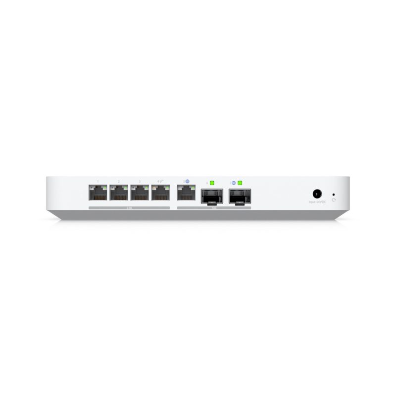
How to handle the issue of Cloud Gateway Fiber access the Luleey XPON module LL-xs2510
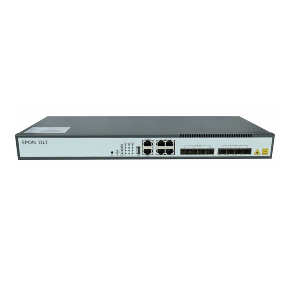
XE Series GPON OLT / EPON OLT WEB USER MANUAL
Common Optical Modules and Interfaces for Switches
Optical Module Compatibility Code: Unveiling the Key to Seamless Connectivity
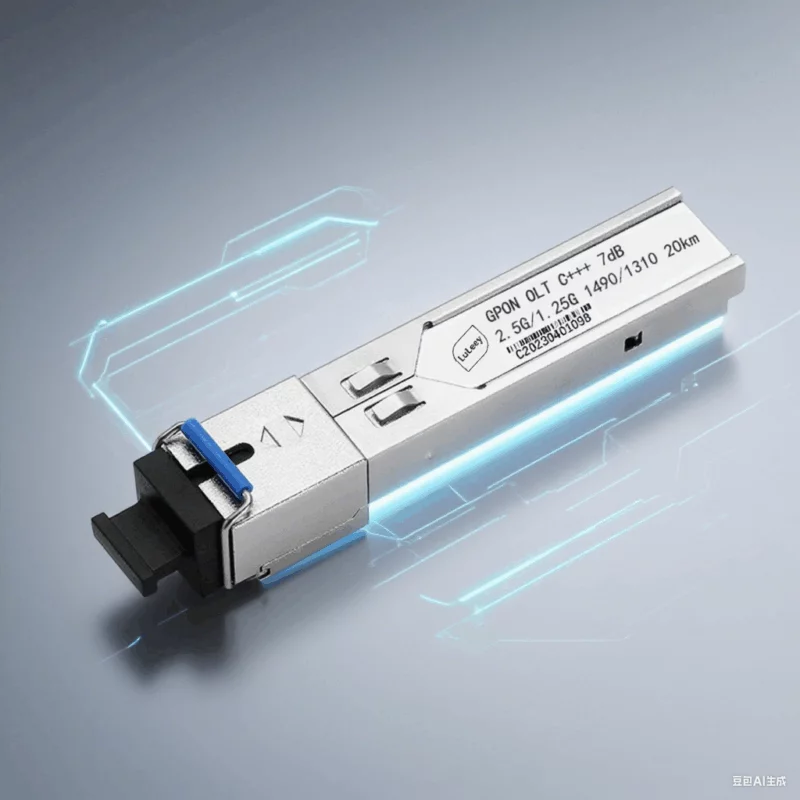
How to choose GPON OLT C+ Module GPON GBIC?
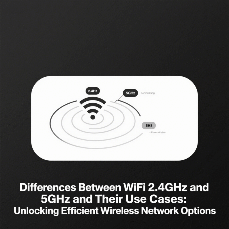
Differences Between WiFi 2.4GHz and 5GHz and Their Use Cases: Unlock
Do you have any question?
Feel free to contact us anytime.
SHOPPING INFORMATION
Over us$39 free shipping.
Europe and North America, Asian can be delivered in about 4-10 days.
Generally, the ship out can be completed within 48 hours.
Yes, an invoice will be sent to you after the shipment is completed.
PAYMENT INFORMATION
PayPal, Credit and debit cards and local payment methods are supported by Stripe.
When you place an order, you need to complete the payment action, after confirming the payment, we will deliver.
Parturient viverra enim torquent elit sociosqu sociis consectetur pretium suspendisse sem scelerisque risus magna est consectetur ullamcorper nunc.
We’re sorry for the bad shopping experience. You can submit a request form or contact us by email. We’ll have a dedicated person to handle it.
Please let us know by email or submit the form online.
Your package is already in transit and can be tracked in My Orders or by mail.

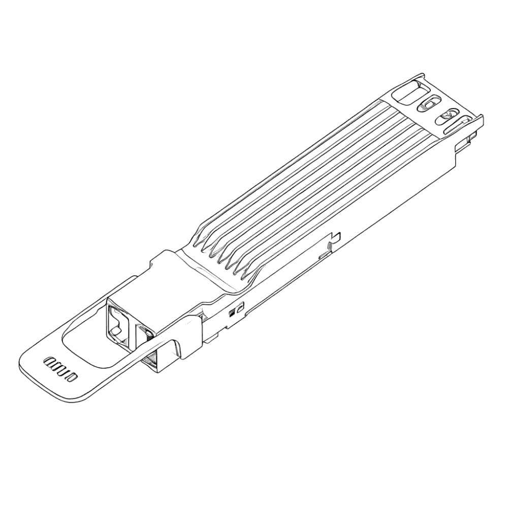


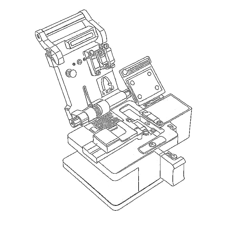
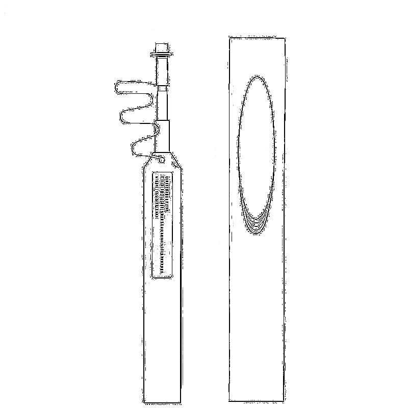
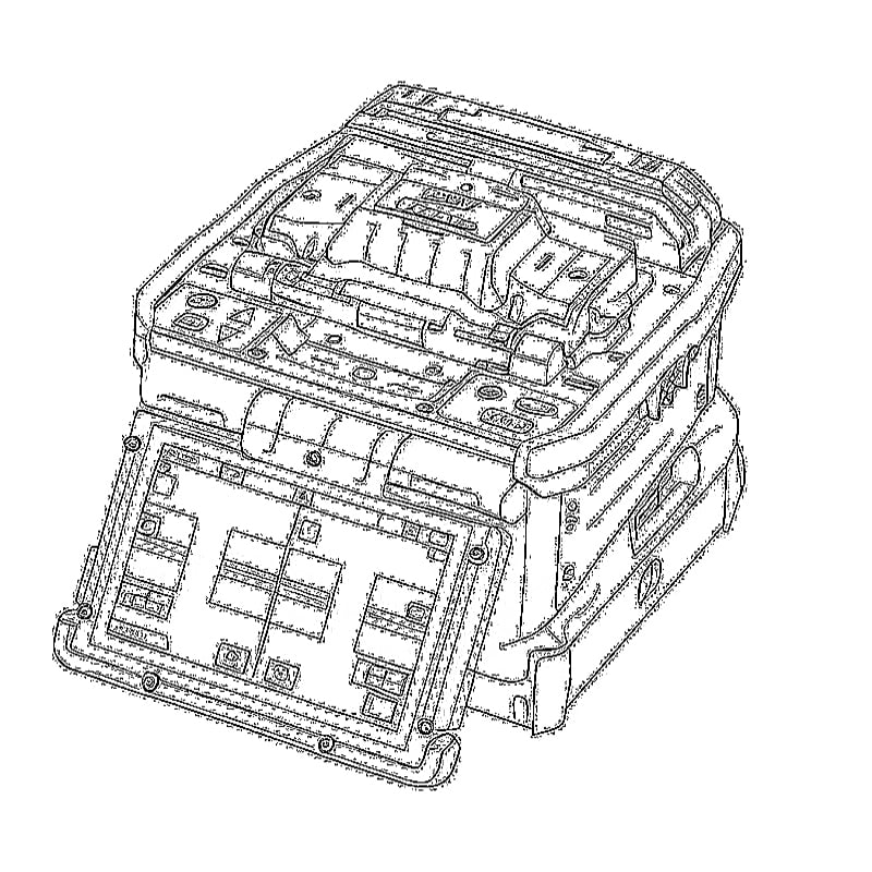
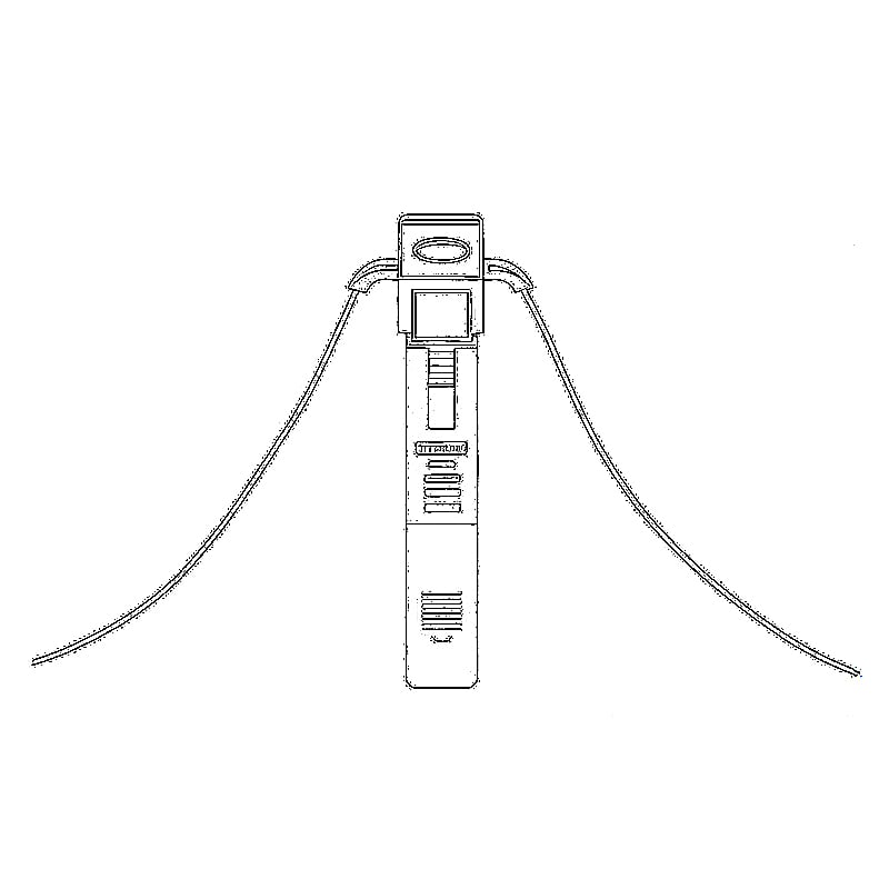




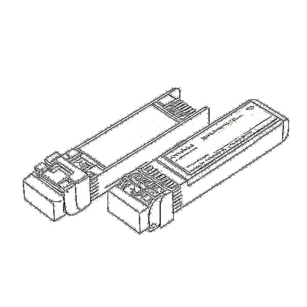 SFP/SFP+ (1G/2.5G/5G/10G)
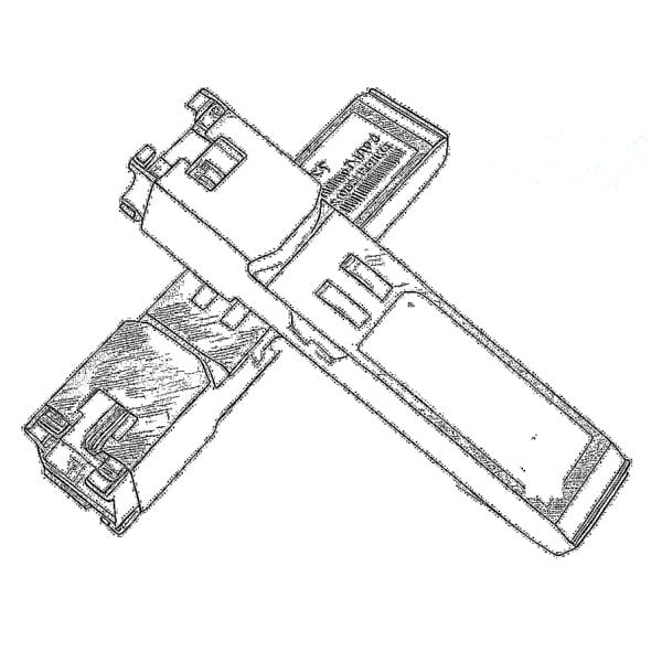 SFP-T (1G/2.5G/10G)
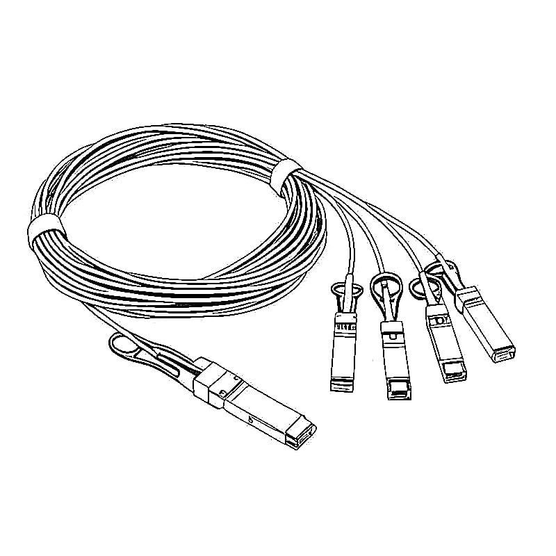
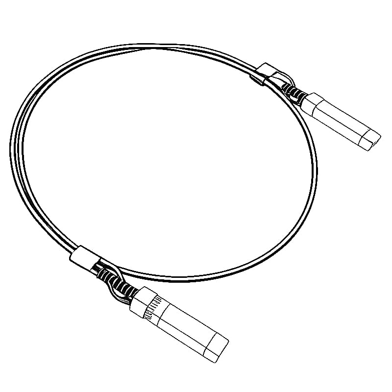
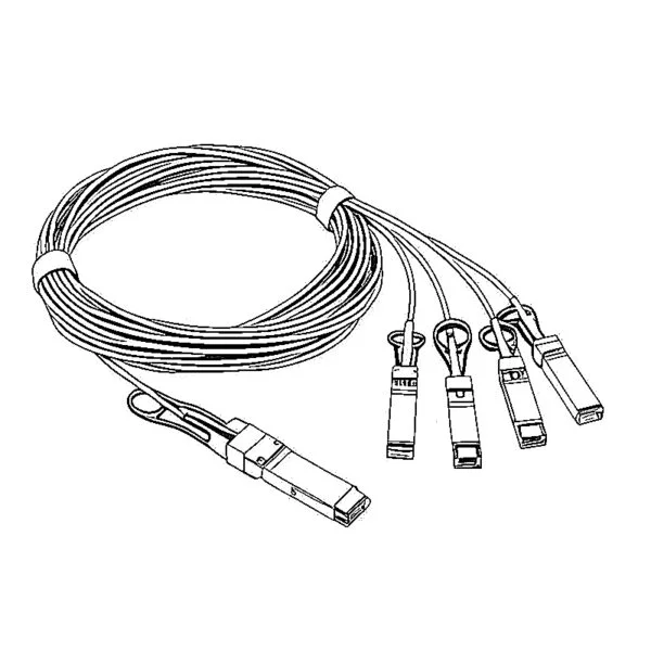 AOC Cable 10G/25G/40G/100G
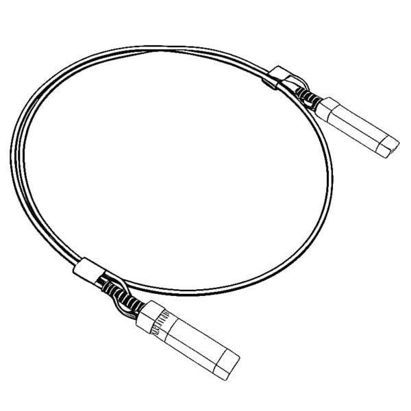 DAC Cable 10G/25G/40G/100G
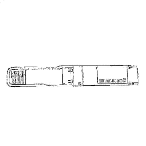 QSFP28 QSFP+ SFP28 100G/40G/25G
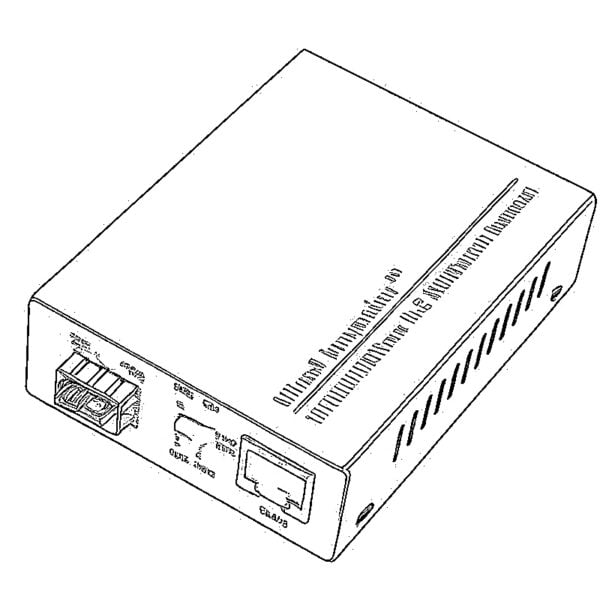
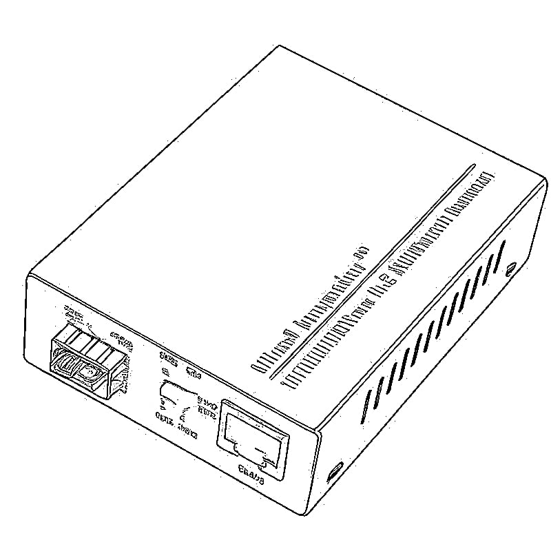
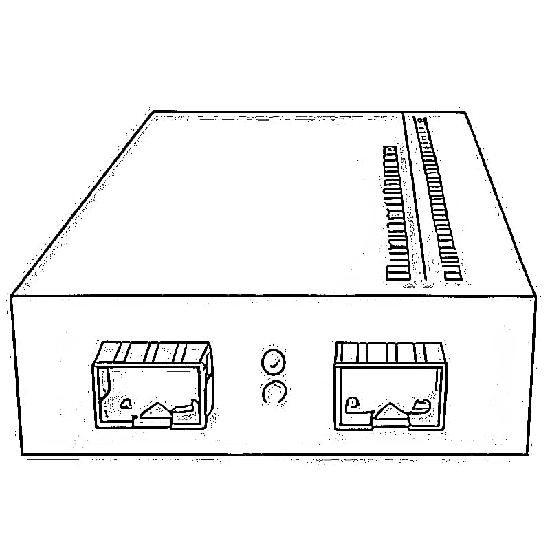
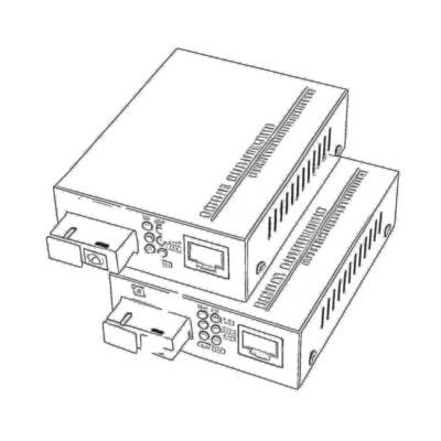 Copper to Fiber Media Converters
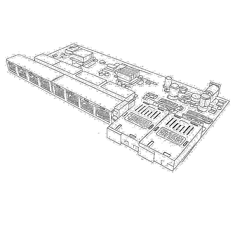
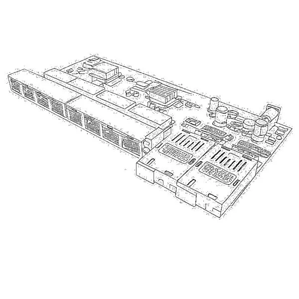 Fiber Media Converter PCBA Board
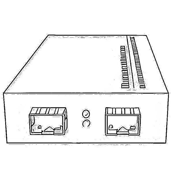 OEO Fiber Media Converters
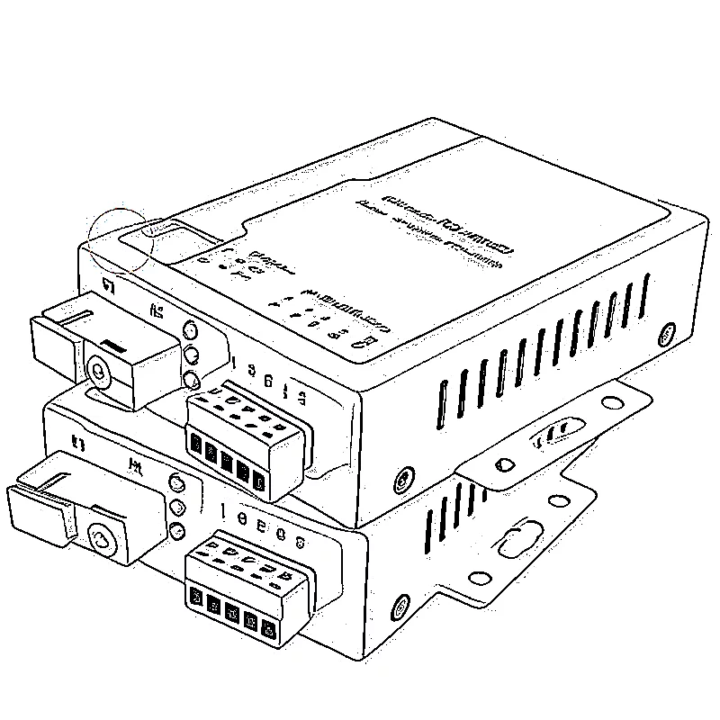
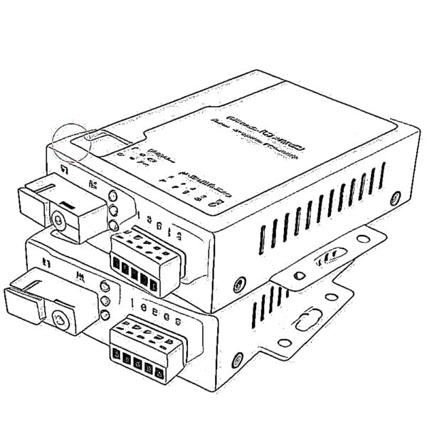 Serial to Fiber Media Converters
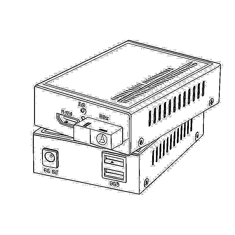
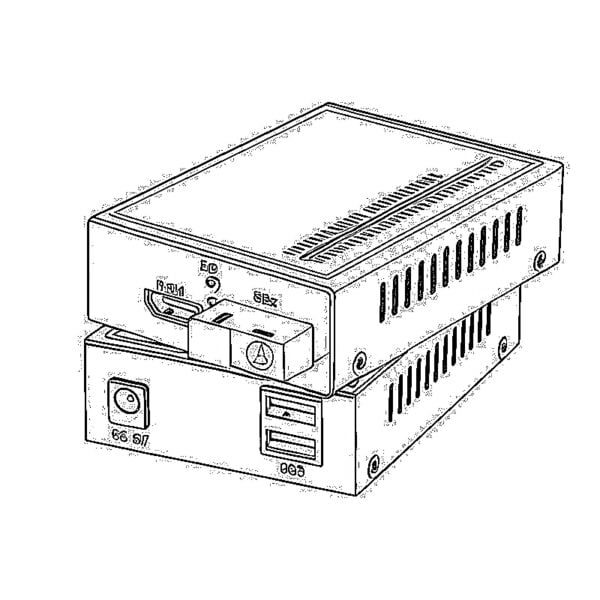 Video to Fiber Media Converters
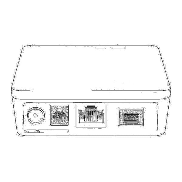 1000M GPON/EPON ONU
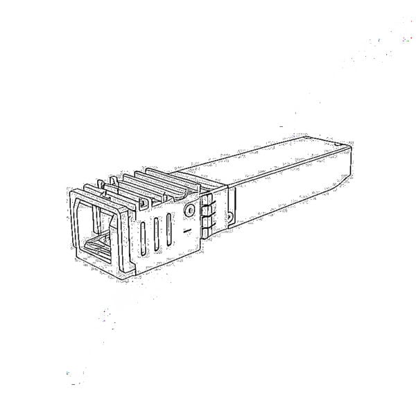 10G EPON ONU/XG-PON/XGS-PON
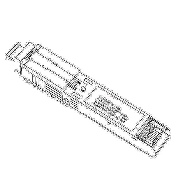 2.5G GPON/XPON STICK SFP ONU
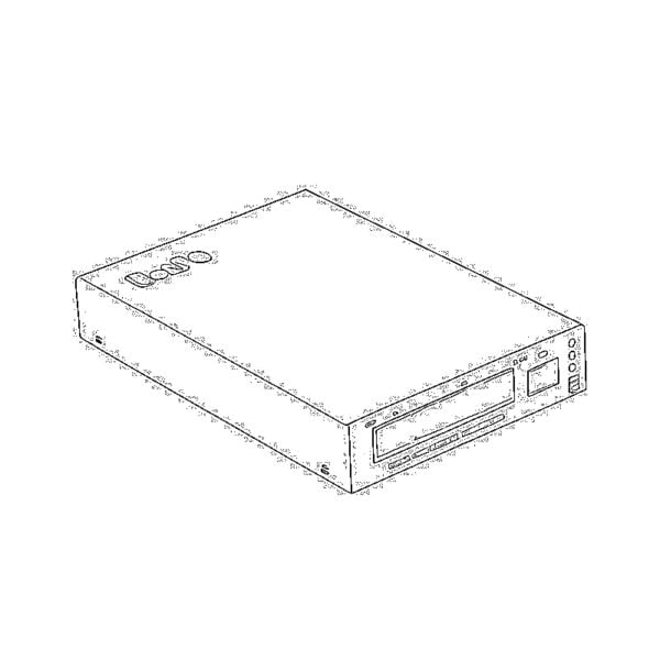 POE GPON/EPON ONU
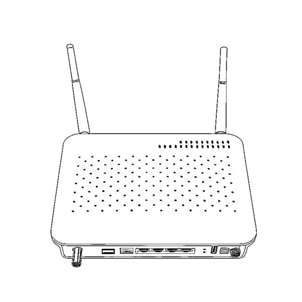 Wireless GPON/EPON ONT
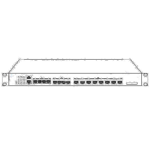 EPON OLT
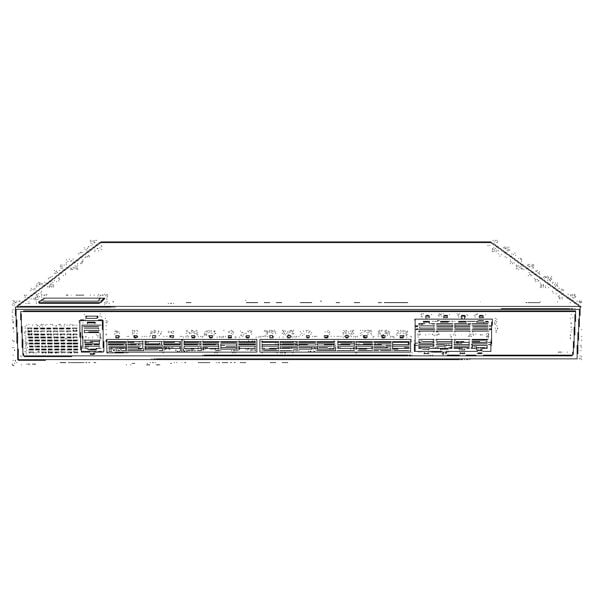 GPON OLT
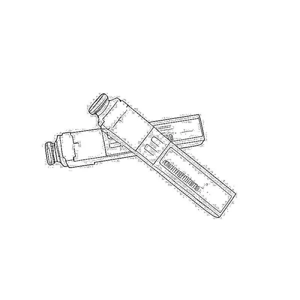 SFP PON Module
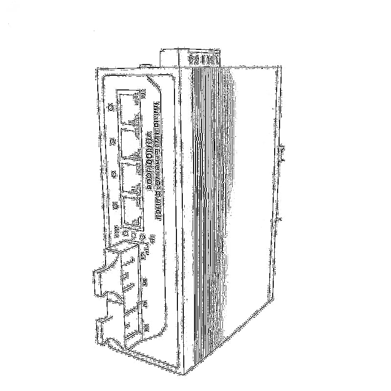
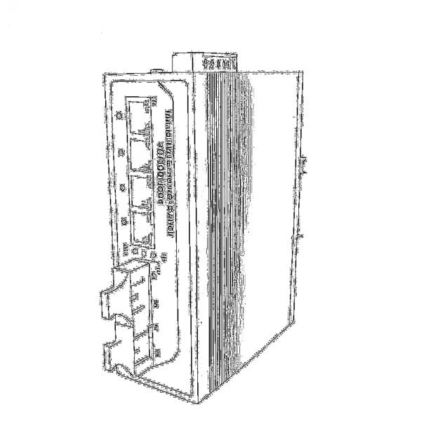 Industrial Switches
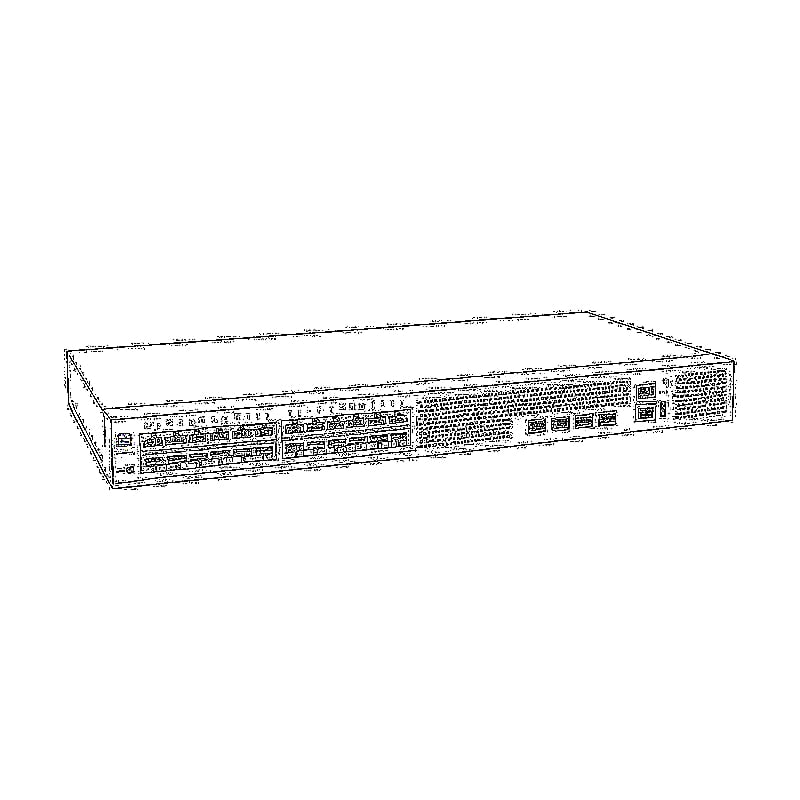
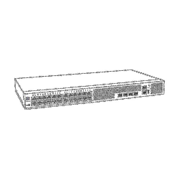 Managed Switches
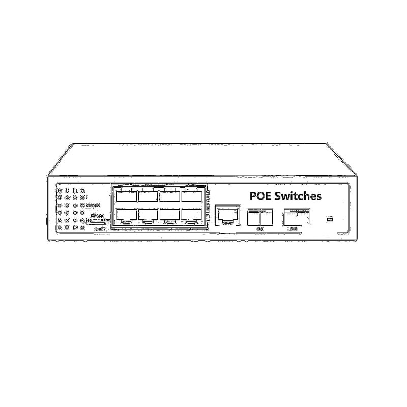
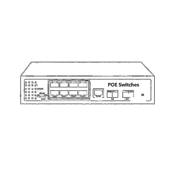 POE Switches
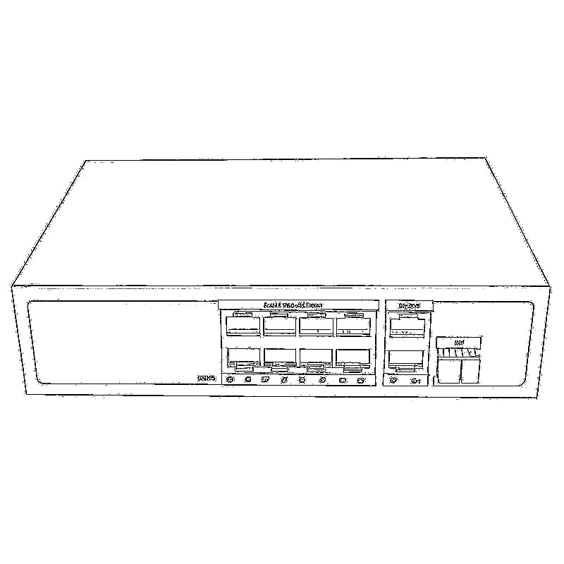
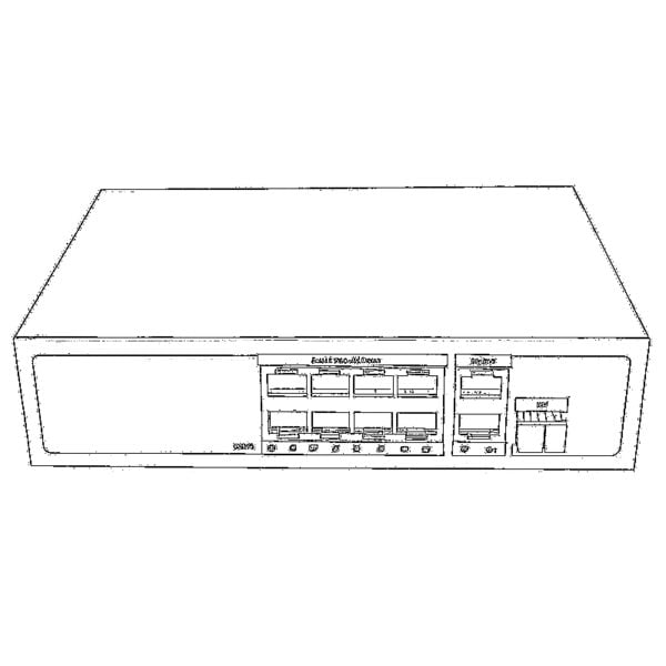 Unmanaged Switches
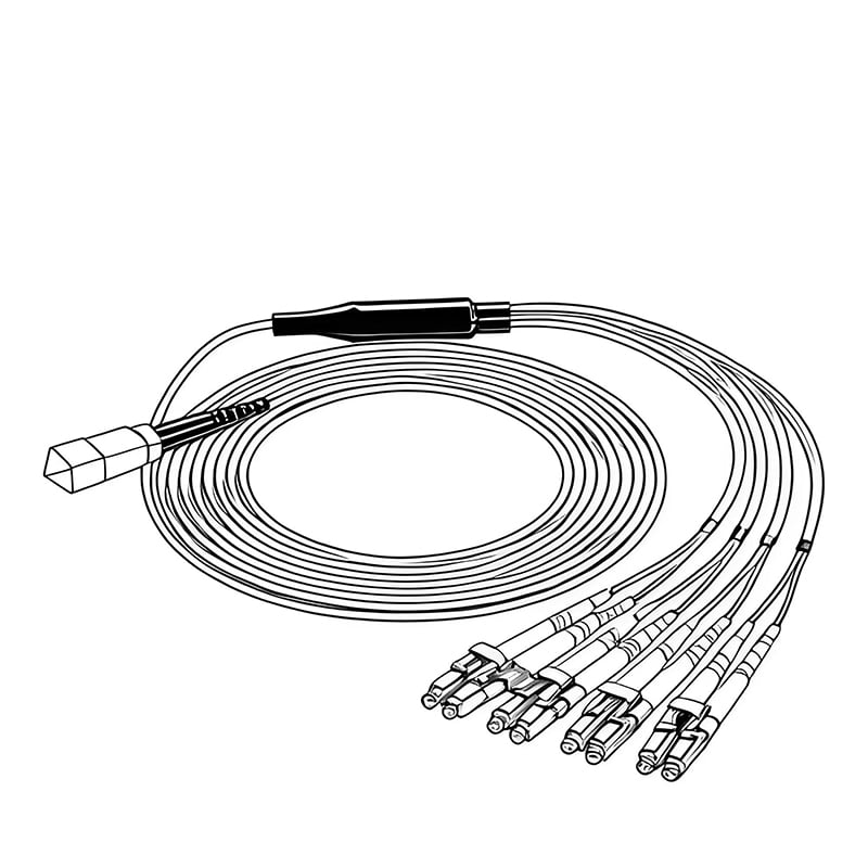
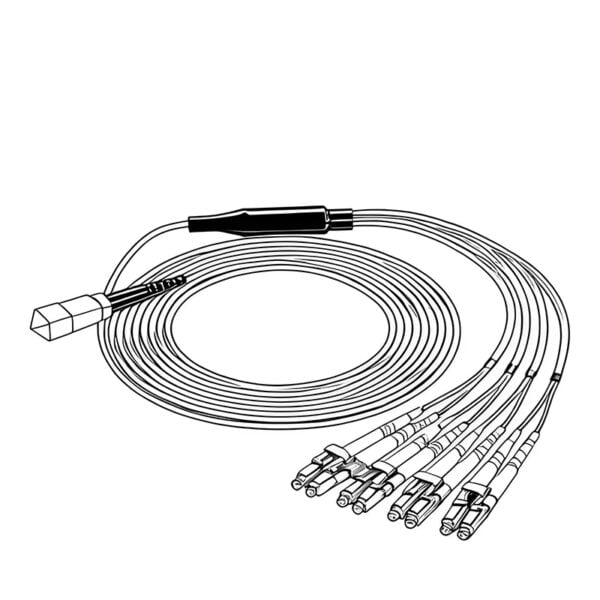 MTP/MPO Fiber Cables
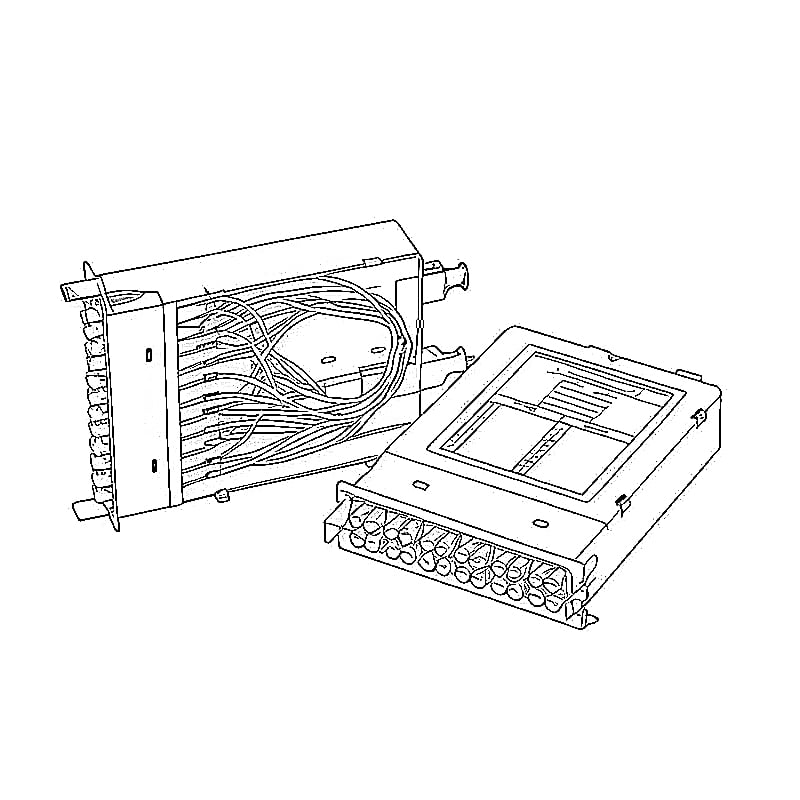
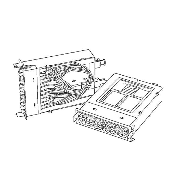 Fiber Optic Cassettes
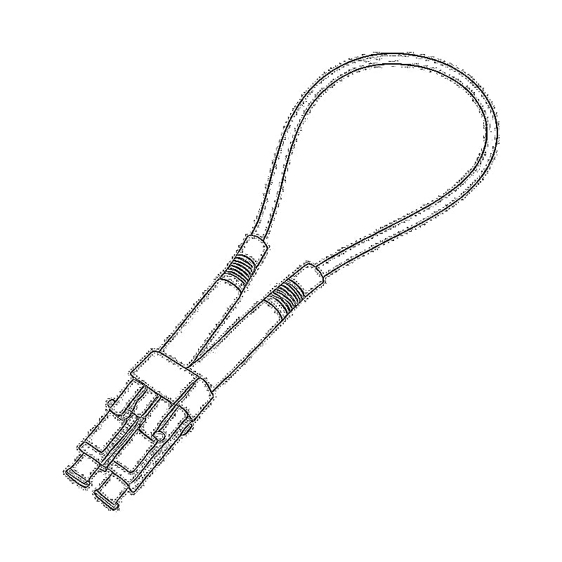
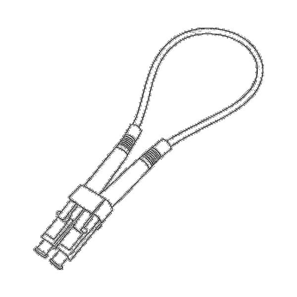 Fiber Optic Loopback
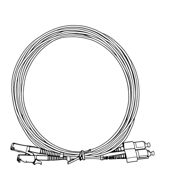
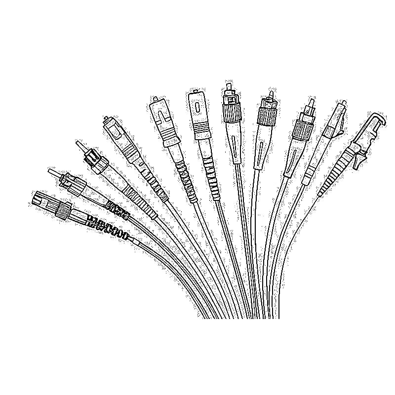
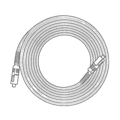 Optic Cables and Fiber Pigtails
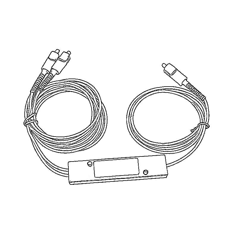
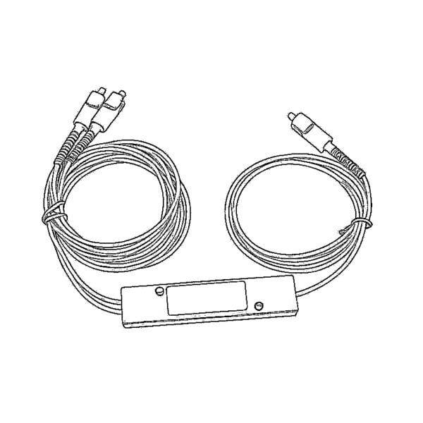 Optical Splitters and Splitter Box
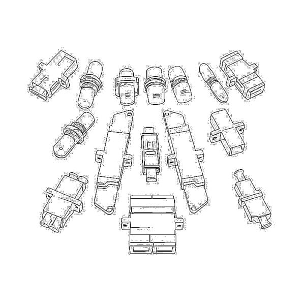
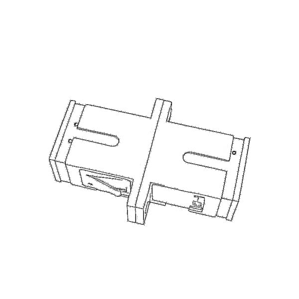 Fiber Flange Connectors
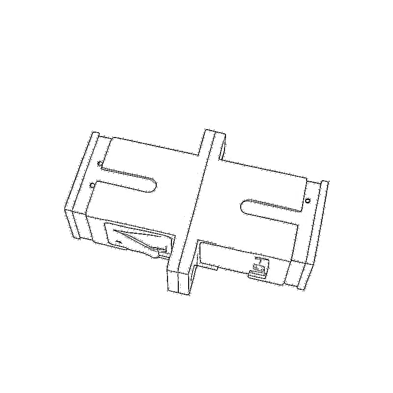
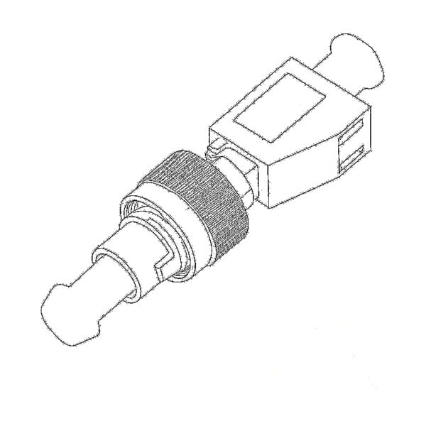 Optical Adapters
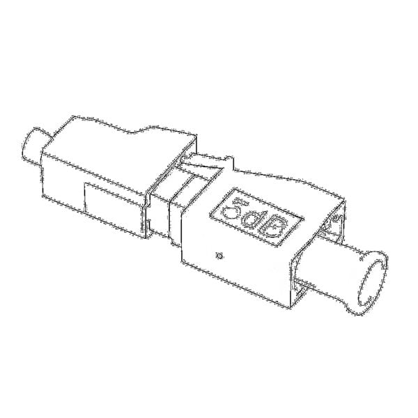 Optical Attenuator
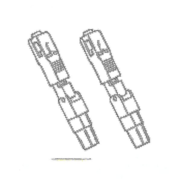 Quick Connector and Connector Panel
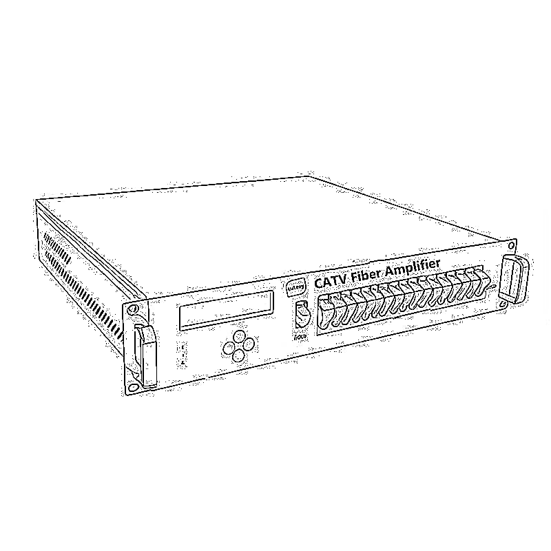
 CATV Amplifier
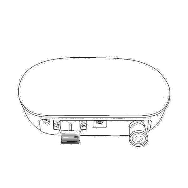 CATV Optical Receiver
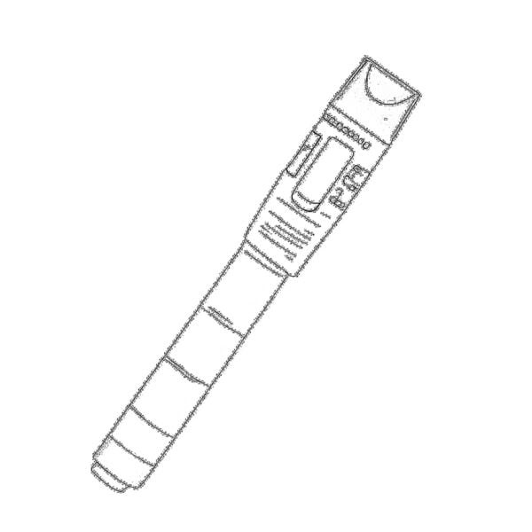 Visual Fault Locator
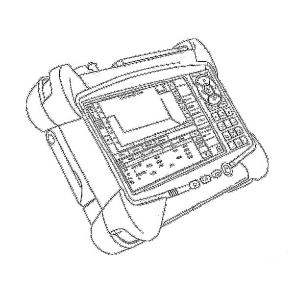 OTDR
OTDR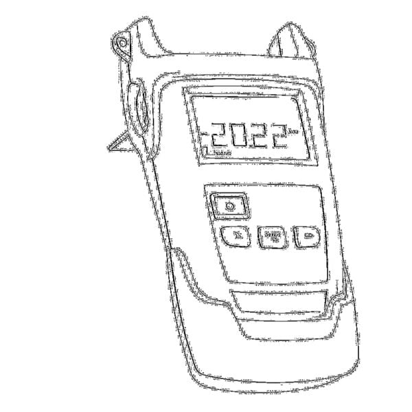 Optical Power Meter
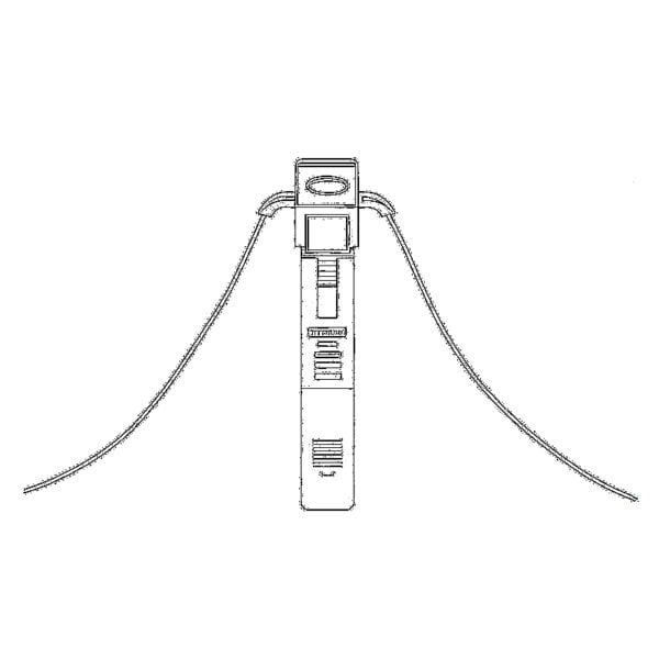 Fiber Optic Identifier
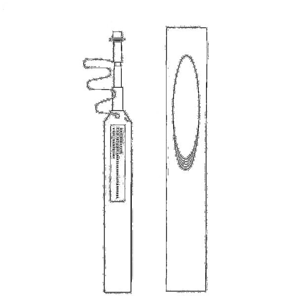 Fiber Optic Cleaners
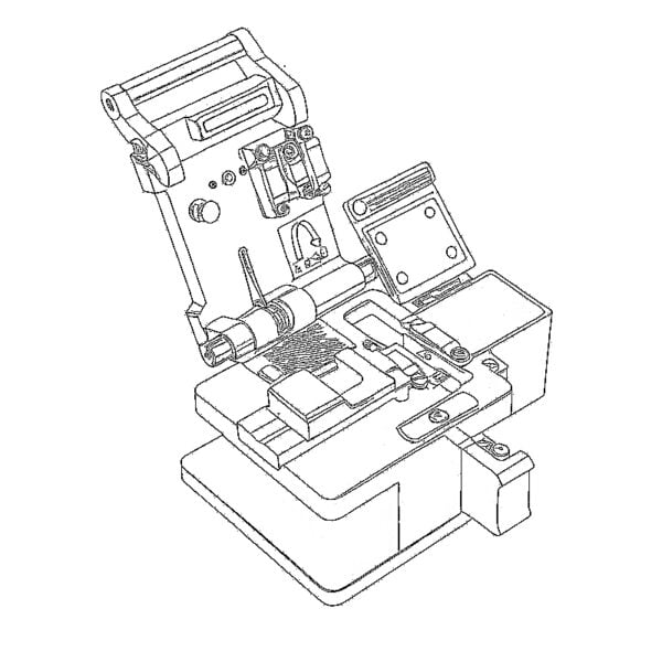 Fiber Cleavers & Fiber Strippers
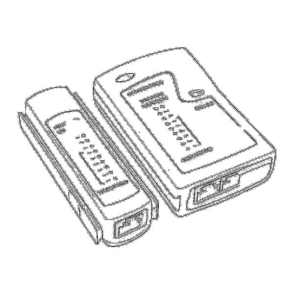 Copper Tools