


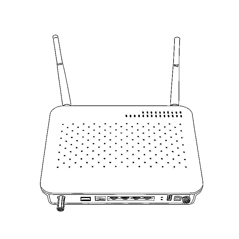
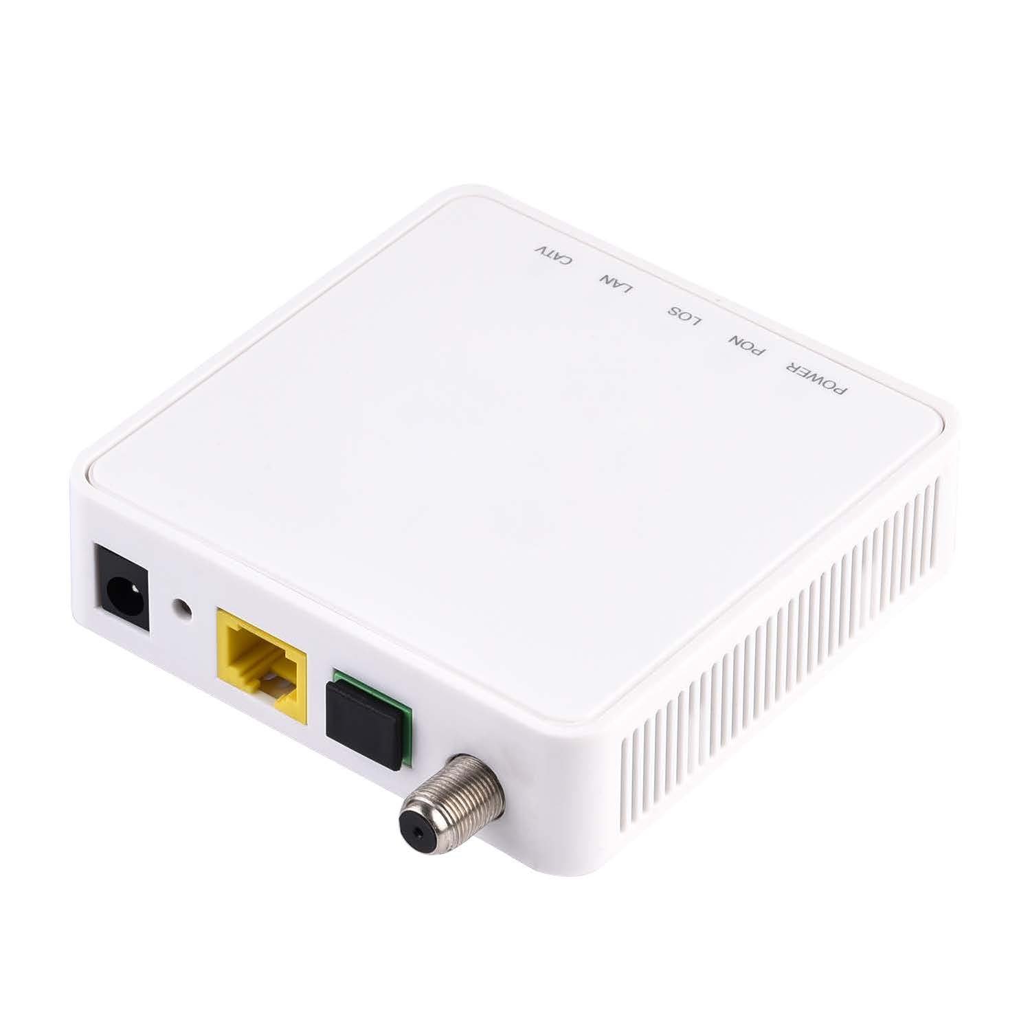


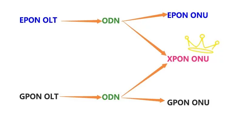
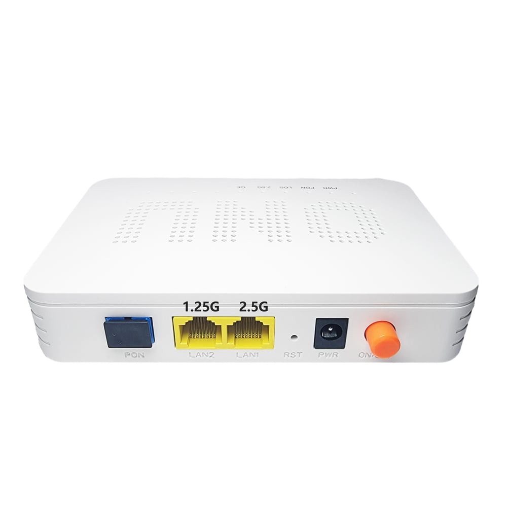
1GE CATV ONU XPON GPON/EPON ONU 1GE+CATV+SCAPC
LL-XP1G1C
Prepare for login the ONUweb management
Before you login the ONU,you should confirm the connect between the ONU and your PC is normal.
Step 1 Configuring the IP address of your PC to 192.168.1.x(2~254) subnet mask is 255.255.255.0
Step 2 Ping IP address of the ONU (Default address is 192.168.1.1).If the PC can get right reply from Ping command,it is mean the connecting between the PC and ONU is normal.
Login ONU
Step 1 Open the explore browser and input the IP address:http://192.168.1.1.
(ONU default IP)
Step 2 You need the user name and password for login.The default username and password are on the label of the ONU bottom.Default administrator user name and password is “admin” and “admin”
( choose the login language here)

Device Status
This page shows the current status and some basic settings of the device.

IPv6 Status
This page shows the current system status of IPv6.

PON Status
This page shows the current system status of PON.

CATV Status
This page shows the current system status of CATV.

LAN Interface Settings
This page is used to configure the LAN interface of your Device. Here you may change the setting for IP addresses, subnet mask, etc..

PON WAN
This page is used to configure the parameters for PONWAN

DHCP Settings
Enable the DHCP Server if you are using this device as a DHCP server. This page lists the IP address pools available to hosts on your LAN. The device distributes numbers in the pool to hosts on your network as they request Internet access.

UPnP Configuration
This page is used to configure UPnP. The system acts as a daemon when you enable it and select WAN interface (upstream) that will use UPnP.

RIP Configuration
Enable the RIP if you are using this device as a RIP-enabled Device to communicate with others using the Routing Information Protocol. This page is used to select the interfaces on your device is that use RIP, and the version of the protocol used.

IP/Port Filtering
Entries in this table are used to restrict certain types of data packets through the Gateway. Use of such filters can be helpful in securing or restricting your local network.

MAC Filtering
Entries in this table are used to restrict certain types of data packets from your local network to Internet through the Gateway. Use of such filters can be helpful in securing or restricting your local network.

Port Forwarding
Entries in this table allow you to automatically redirect common network services to a specific machine behind the NAT firewall. These settings are only necessary if you wish to host some sort of server like a web server or mail server on the private local network behind your Gateway’s NAT firewall.

DMZ Configuration
A Demilitarized Zone is used to provide Internet services without sacrificing unauthorized access to its local private network. Typically, the DMZ host contains devices accessible to Internet traffic, such as Web (HTTP) servers, FTP servers, SMTP (e-mail) servers and DNS servers.

User List
This table shows a list of learned MAC addresses.

BridgingConfiguration
This page is used to configure the bridge parameters. Here you can change the settings or view some information on the bridge and its attached ports.

RoutingConfiguration
This page is used to configure the routing information. Here you can add/delete IP routes.

IPv6 Configuration
This page be used to configure IPv6 enable/disable

RADVD Configuration
This page is used to setup the RADVD’s configuration of your Device.

DHCPv6 Settings
This page is used to configure DHCPv6 Server and DHCPv6 Relay.

IPv6 Static Routing Configuration
This page is used to configure the IPv6 static routing information. Here you can add/delete static IP routes.

IPv6 IP/Port Filtering
Entries in this table are used to restrict certain types of data packets through the Gateway. Use of such filters can be helpful in securing or restricting your local network.

Ping Diagnostics
This page is used to send ICMP ECHO_REQUEST packets to network host. The diagnostic result will then be displayed.

Diagnostics — Loop Detection
This page is used to configure loop detection parameters. Here you can change the settings or view loop detection status.

GPON Settings Multicast Vlan CATV Settings OMCI Information Commit/Reboot Multi-lingual Settings Backup/Restore Password Firmware Upgrade ACL Time Zone TR-069

Interface Statisitcs
This page shows the packet statistics for transmission and reception regarding to network interface.

PON Statistics

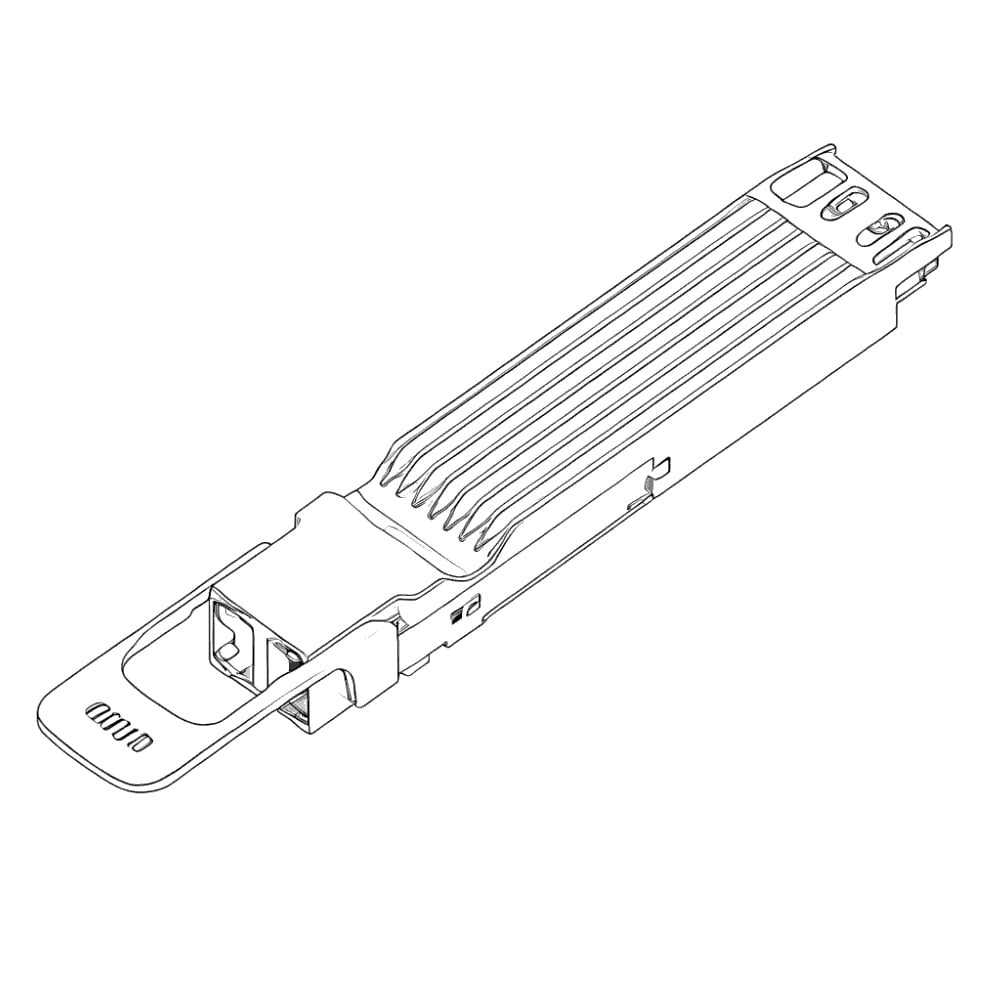
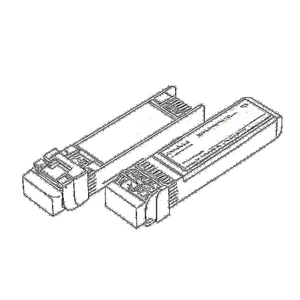 SFP/SFP+ (1G/2.5G/5G/10G)
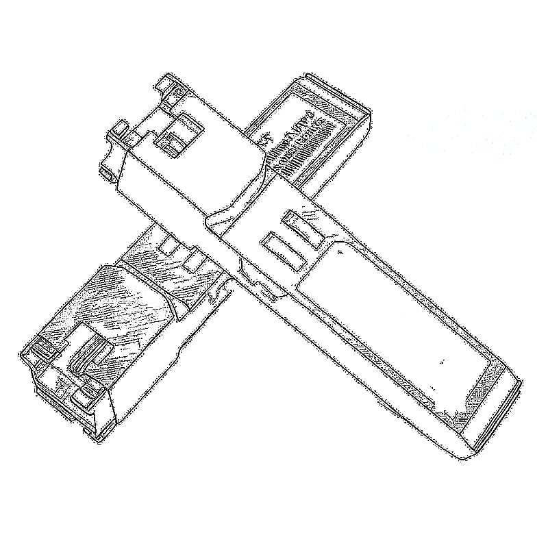
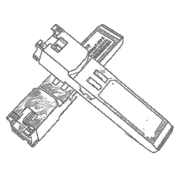 SFP-T (1G/2.5G/10G)
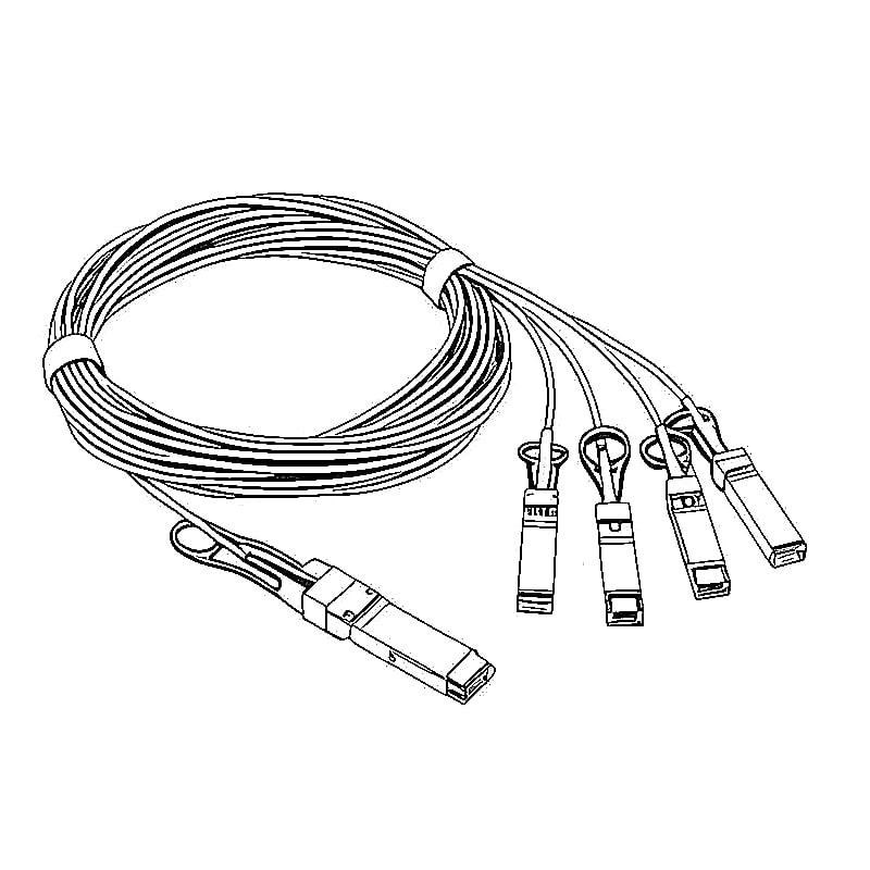
 AOC Cable 10G/25G/40G/100G
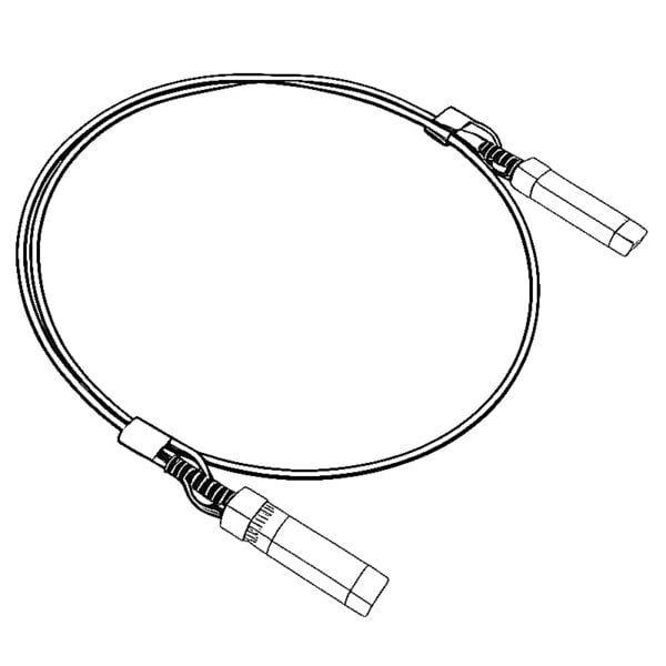 DAC Cable 10G/25G/40G/100G
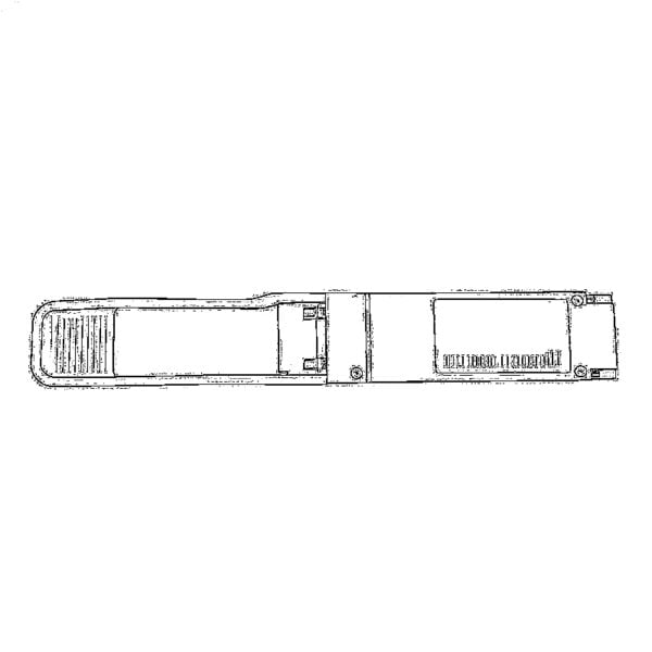 QSFP28 QSFP+ SFP28 100G/40G/25G
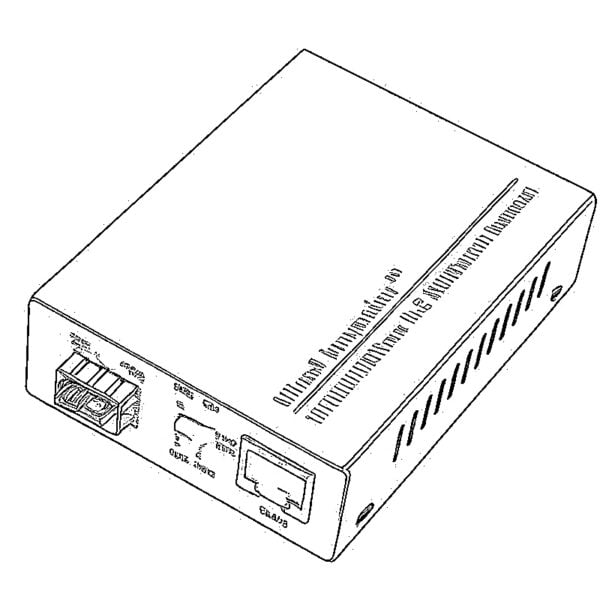
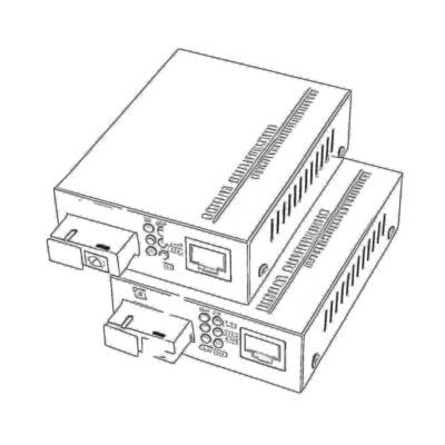 Copper to Fiber Media Converters
 Fiber Media Converter PCBA Board
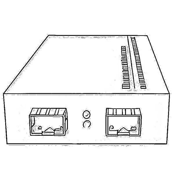 OEO Fiber Media Converters
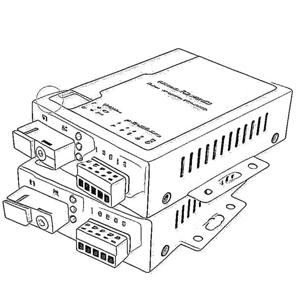 Serial to Fiber Media Converters
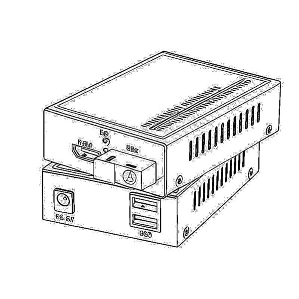 Video to Fiber Media Converters
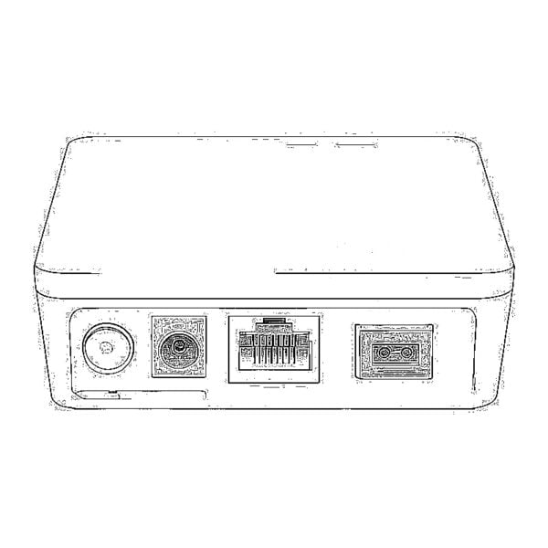 1000M GPON/EPON ONU
 10G EPON ONU/XG-PON/XGS-PON
 2.5G GPON/XPON STICK SFP ONU
 POE GPON/EPON ONU
 Wireless GPON/EPON ONT
 EPON OLT
 GPON OLT
 SFP PON Module
 Industrial Switches
 Managed Switches
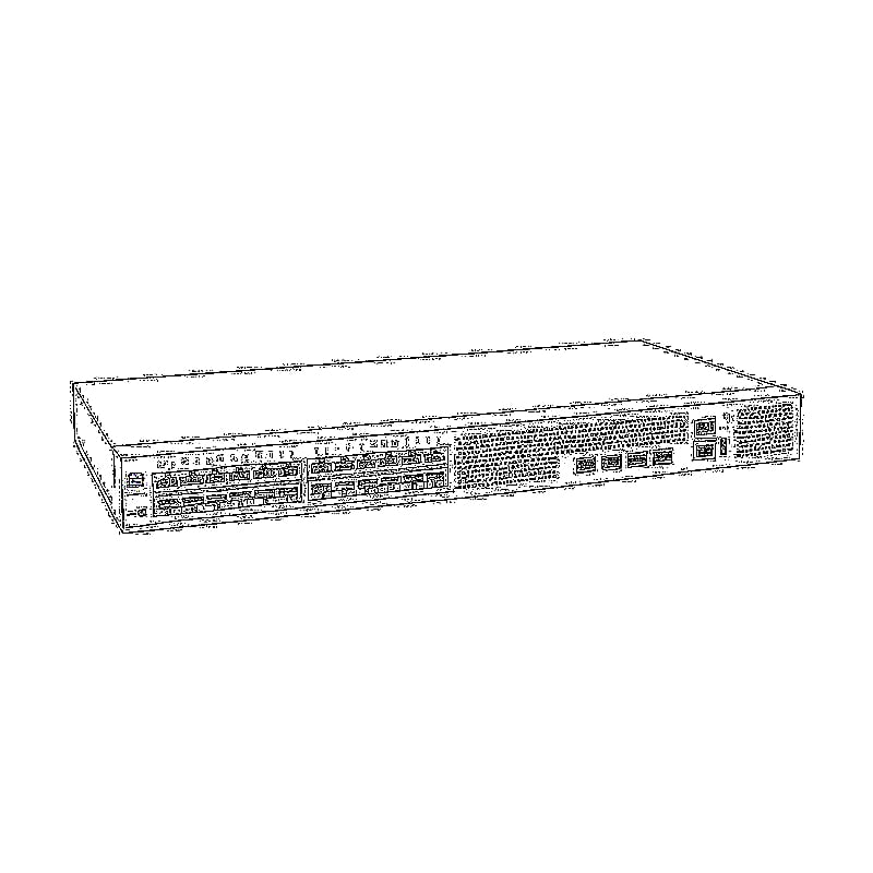
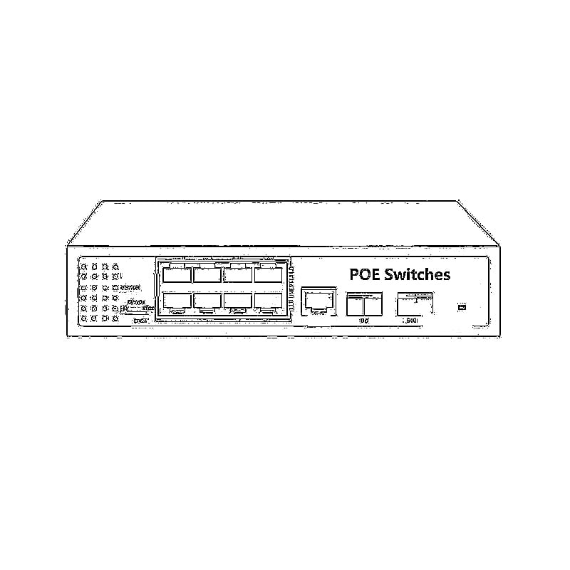
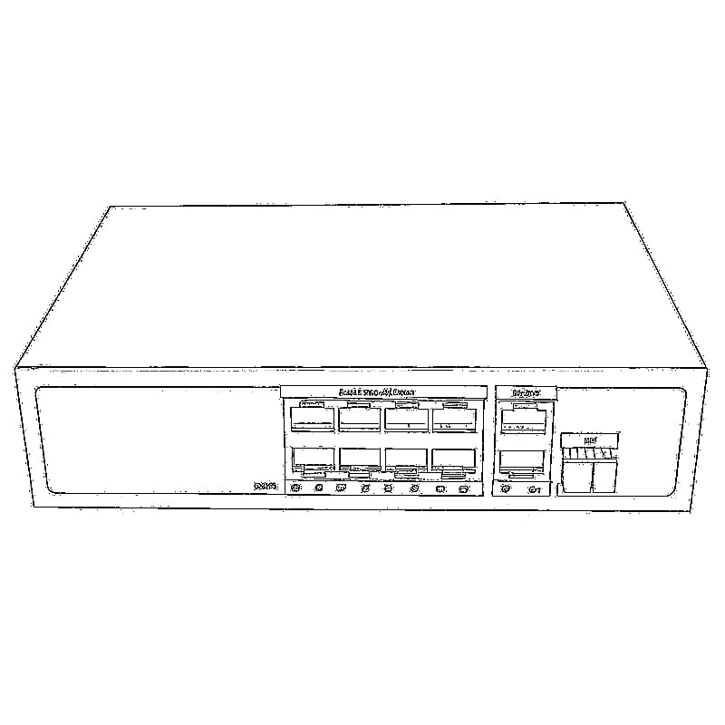
 POE Switches
 Unmanaged Switches
 MTP/MPO Fiber Cables
 Fiber Optic Cassettes
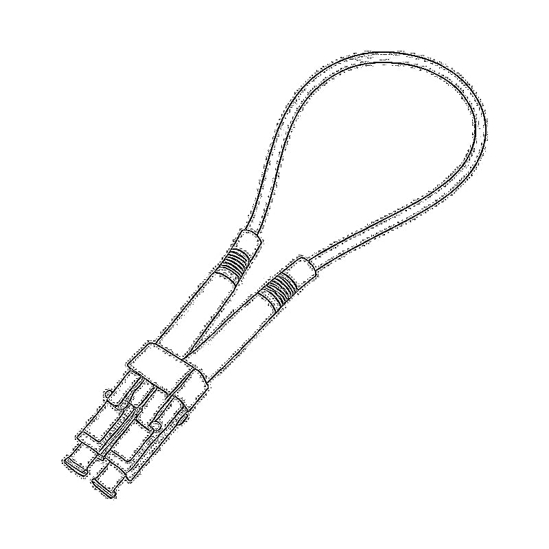
 Fiber Optic Loopback
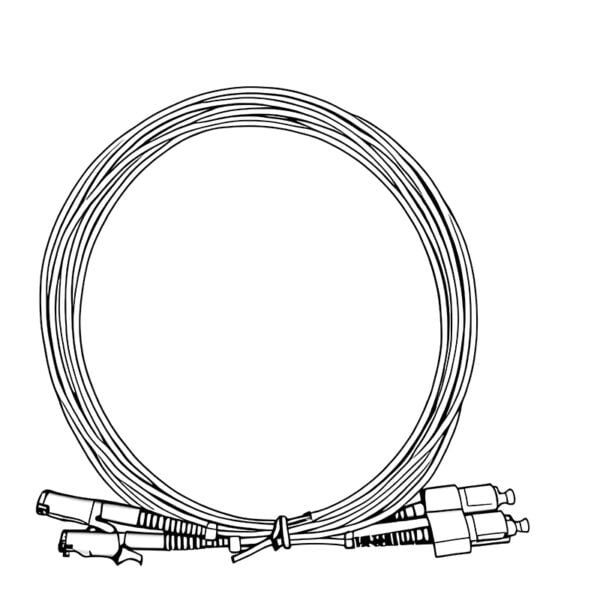
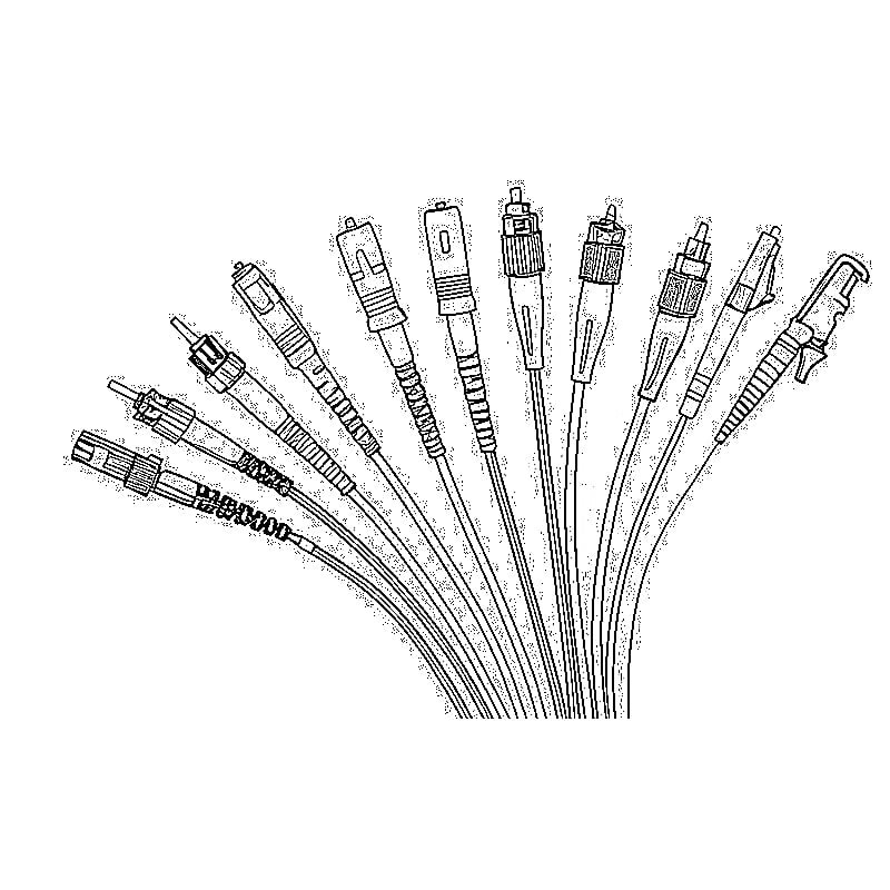
 Optic Cables and Fiber Pigtails
 Optical Splitters and Splitter Box
 Fiber Flange Connectors
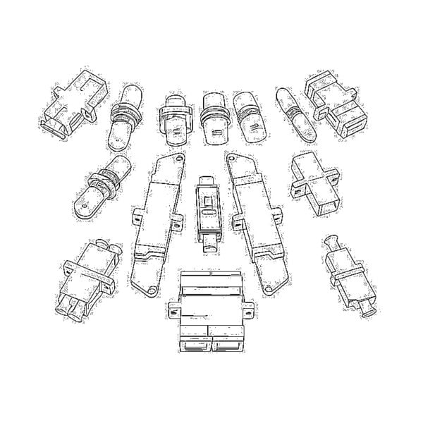
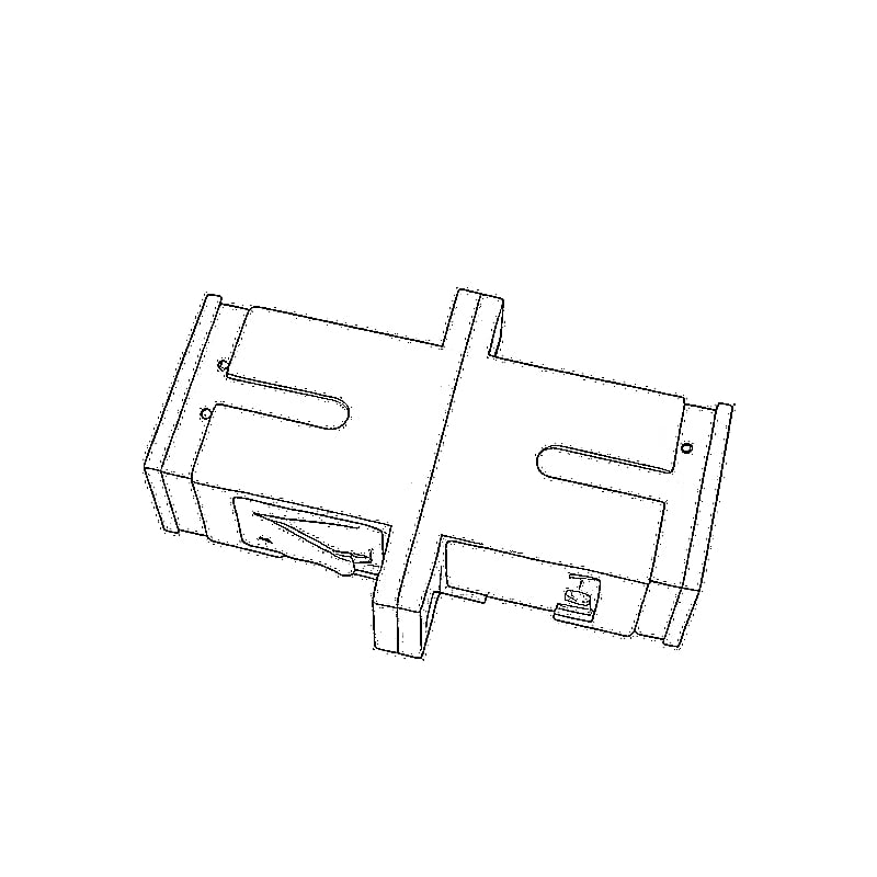
 Optical Adapters
 Optical Attenuator
 Quick Connector and Connector Panel
 CATV Amplifier
 CATV Optical Receiver
 Visual Fault Locator
 OTDR
OTDR Optical Power Meter
 Fiber Optic Identifier
 Fiber Optic Cleaners
 Fiber Cleavers & Fiber Strippers
 Copper Tools